
Solar Installation Series – Part 7
Introduction
A rapid shutdown system is not only a great thing to have for your solar power system, it is likely a requirement. In this post, I will cover the Tigo rapid shutdown system that I have installed on my solar installation.
Get up to date on this series by reviewing the previous posts.
Part 1: Solar Power System – Design and Planning
Part 2: Unique Roof Mounts for Solar Panels
Part 3: Lifting Solar Panels – Innovative Solutions
Part 4: Quick Tips for DIY Solar Panel Installation
Part 5: The Ultimate Guide to Building a Solar Equipment Shed
Part 6: Guide to Wiring Solar Power Equipment
What is a Rapid Shutdown System?
A rapid shutdown system is a piece of safety equipment for your solar power system. Solar panels put power into your system any time there is light hitting their surface. This happens, whether or not the rest of your system is able to receive that power. Solar panels just don’t care.
In the event of a catastrophic failure in the system, when simple isolation switches are not enough (or are disabled), or a fire breaks out in the building, enable rapid shutdown. This is to keep people working on your building, especially fire fighters safe from electric shock. Electrical problems are often a cause of fires, so disconnecting power from the building is a key safety measure.
This is great piece of mind to have, but it is also a code requirement for roof mounted arrays, and has been since 2017 (longer in some places). The system is required to reduce the line voltage to less than 30V and 240VA within 30 seconds. All roof-mounted arrays need RSS modules, but ground arrays do not.
Equipment
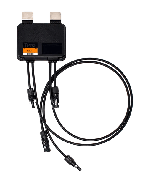
In order to have a functioning rapid shutdown system, you need to have the right equipment. Each panel on the roof needs to have a rapid shutdown module. For my installation, I went with the Tigo TS4-A-F, which is a RSS only module. You can choose to purchase optimizing modules that have RSS built in, but I don’t have to worry about shade, so I just used the basic RSS module.
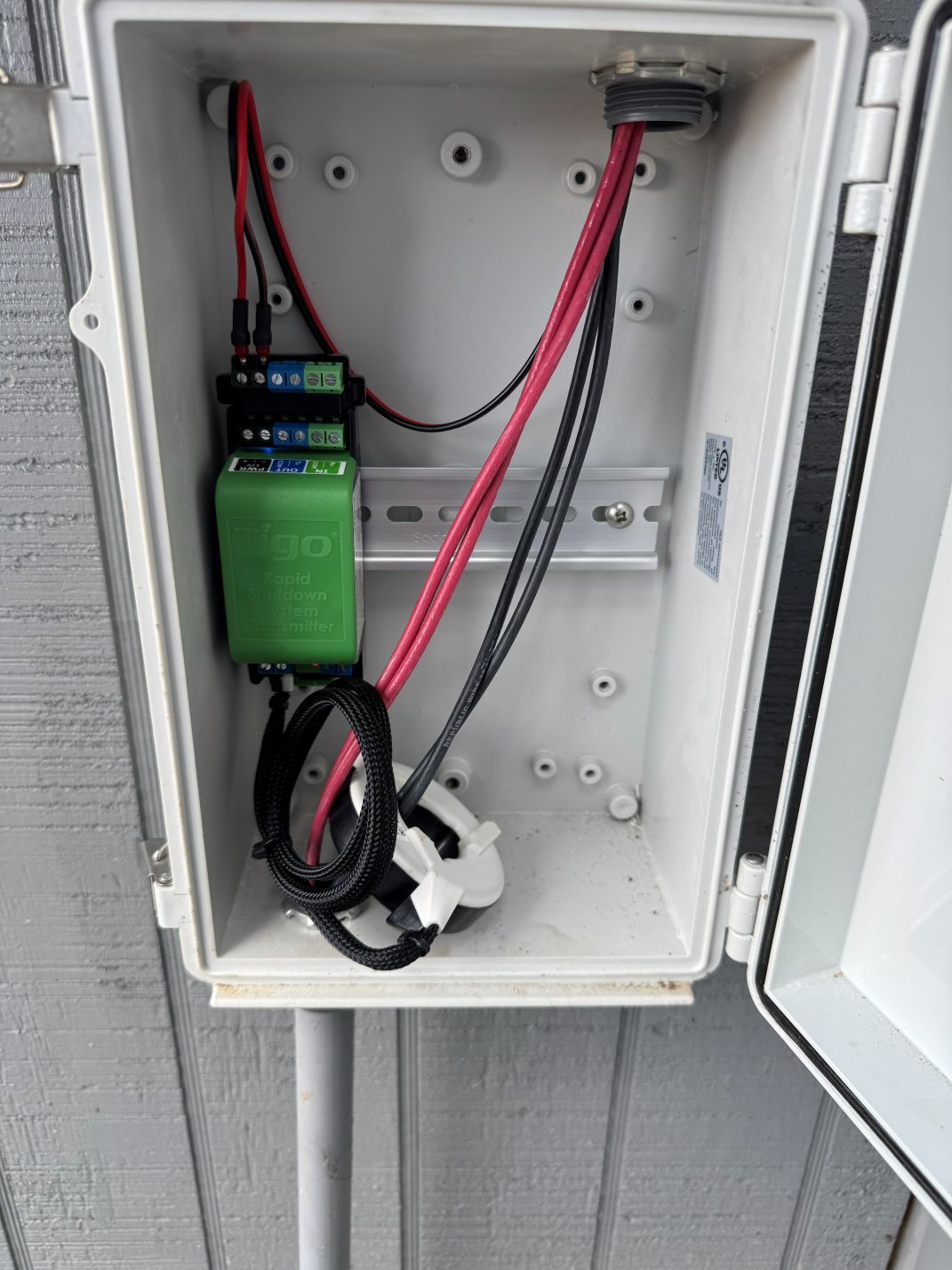
The Tigo TS4-A-F is the receiver of the signal for the rapid shutdown. In order to send the signal you need to have an RSS transmitter. For my system, we have the RSSx transmitter, which is has pure signal technology. The RSSx uses power line communications (PLC) to send the signal through the home runs of the solar strings. The signal core is what sends the signals through the wires. The signal cores and transmitters are purchased together as the cores cannot be purchased separately.

The inverter is the EG4 6000xp and the batteries are the EG4 Wall Mount All Weather. On the 6000xp, it has connections for the rapid shutdown system built in. There is a place to connect the switch and there is a place for power to the module. If your inverter does not have a power source for the transmitter, you’ll have to run power to the device.

Installation
Tigo supplies a weatherproof box to house the RSS transmitter and the signal core. In my setup, I installed the Tigo box below the maintenance switch box, so that even if I had the maintenance switches turned off, the RSS would still function. My box is on the side of the solar equipment building and the switch is mounted to the side of the maintenance box.


To install, connect stable 12V power to the labeled terminals. A stable 12V power supply is essential for this to operate as the 12V power is a “keep alive” signal for the transmitter. Which means that as long as the transmitter is receiving 12V of power, it will keep the solar array active. If the module were to loose that voltage through a problem, or manual trigger (hitting the big red button), the system will shutdown the modules on the solar panels.
Next, route the negative wires for the solar strings through the signal core. Make sure the core is oriented where the black side is towards the solar panels (wire origin) and the white side is towards the inverter (wire destination). The polarity of the signal core matters! Each core can handle up to ten strings of solar arrays. You can purchase RSS transmitters that come with two signal cores. You can also daisy-chain the transmitters to have up to ten transmitters working together for large commercial applications.

In order to be compliant with codes and for safety reasons, please make sure to put the appropriate placards on the equipment so first responders can easily locate the switch. These pictures were taken before my placards arrived.
Operation
In order to trigger the rapid shutdown sequence, you need to hit the big red button (on my system). When that occurs several things happen in my system. I’m not sure of the exact order everything is triggered because it happens fast.
The inverter reads the signal from the switch and cuts the 12V power to the RSS transmitter. When the 12V power is lost, the “keep alive” signal in the signal core stops and causes the modules on the roof to go into shutdown mode, limiting the voltage from the panels.
I can’t speak for other systems out there, but the EG4 system also shuts down every inverter past the master inverter (where the switch is plugged into). It triggers Energy Storage System (ESS) disconnect, which trips the breakers on all batteries, isolating them from the system. When the system is activated, all power is cut to the building.
To get the system back on, you need to reset the switch and restart your system. One thing that it doesn’t mention, that I had to find out the hard way, was resetting the batteries. You can’t just flip the breakers back on, it will not allow you to do that. You first need to push the power button to turn the batteries off, then flip the breakers back on, and power the batteries up in their intended sequence.
Thank You
Thank you for reading my post. If you find that you gained some knowledge and would like to read more, please consider giving us a like and subscribing. It’s free and it helps us get sponsors for future content. Also if you feel we are worthy of a small donation, you can leave a tip at the button below. Every little bit helps as the projects can be quite costly.
Leave a Reply