Solar Installation Series – Part 5
Introduction
Building a solar equipment shed is an excellent way to store large, and potentially dangerous equipment in a safe and space-saving manner. In this post we will cover the design and safety considerations of such a building.
Get up to speed on the previous posts in this series.
Part 1: Solar Power System – Design and Planning
Part 2: Unique Roof Mounts for Solar Panels
Part 3: Lifting Solar Panels – Innovative Solutions
Part 4: Quick Tips for DIY Solar Panel Installation
Building Design
The building that I put the solar panels on is 960 square feet on the inside. Because I need open space inside, I did not want to put the batteries and inverters in the building. They would require too much space. The next best option was to build a separate shed outside to house the solar equipment.
Design Considerations
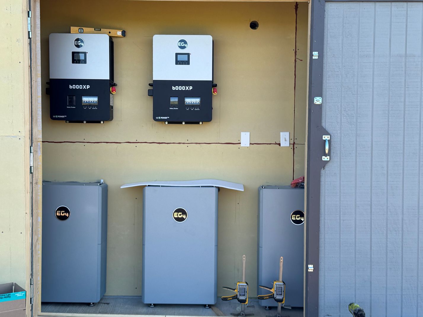
I have three EG4 All Weather batteries and two EG4 6000XP inverters. I foresee possibly needing to add on to the system at some point in the future, so I designed the solar equipment shed to handle up to 5 batteries and 4 inverters if needed. The batteries need to have a minimum of 12 inches on all sides (except the floor side), but also need to be close enough to the inverters for the cables to reach. The inverters need 8 inches clearance to the sides and just under 20 inches of clearance vertically.
The batteries are very heavy! They weigh 308.6 lbs (140 kg) each. They come with wall mounting brackets, but they also have feet on the bottom. You can hang them entirely on the wall, or a combination of sitting on their feet and anchored to the wall. They should be anchored to the wall because they are thin and tall and therefore at risk of toppling over. The inverters weigh 53 lbs (24 kg) each. They need to be mounted on a wall, and preferably just above the batteries for best cable management.
Safety
Despite all the negativity about lithium ion batteries, they are quite safe. So are gas ranges, fireplaces, and hair dryers. Whether or not an item is a known safety risk or not, you should always give it the respect it deserves.
Lithium batteries (as well as all other batteries) are energy storage devices. That means that if they are damaged in some way, they contain a lot of energy that can be released. Usually that energy release is in the form of heat, which can be hot enough to start a fire. A problem that is more specific to lithium batteries is that they off-gas hydrogen and other hydrocarbons that can sustain a combustion (fire). This is the main safety concern about lithium battery fires. They are difficult to put out because they are self-sustaining.
Whether you want to address these concerns or not, local regulations often require you to. For me, my batteries need to be mounted to a fire resistant wall such as concrete or other fire rated material.
Design

The ultimate design centered on a wide, yet shallow shed with a large opening to access and service the solar equipment. The building is 16 feet wide, and 2.5 feet deep. The roof has a 4/12 pitch. The whole structure is anchored to a four inch thick concrete pad with five 8 inch pylons that extend 3 feet into the ground. The pylons used because the top foot of soil in that area is fill dirt and not very stable. I wanted to make sure this building had a stable foundation.
If you notice in Figure SI-5-2, the concrete slab sits a few inches away from the building. This is just another safety feature I decided to implement. In addition to the fire resistant materials for the walls, I wanted to create an air gap between the two buildings. Air is a great insulator. If there were to be a fire, this gap can really delay the main building from catching on fire.

Construction
One thing about me is that I like to plan my builds ahead of time and I also like to pre-build my structures as much as possible. This was especially true for the back wall. Since it would be close to the main building, but not touching, it meant that it needed to have siding. If I built the wall in place, I would not be able to put the siding on the correct side of the wall. So I pre-built the walls and used the tractor to move them into place.


Door Header
On the front wall, there is a large door opening. The doors are each six feet long, so that means a 12 foot opening. Normally for a large opening it requires a thick header, possibly an engineered beam. However, this shed will have minimal weight above the door. It will support the roof, but that is a very small roof. The building is only 2.5 feet from the front to the back, so the weight of the roof is not much of a factor. As a result, I decided to make a box beam out of four 2×4’s.

Roof
Like I said earlier, I like to pre-build my parts. In this case, since the weather was nice, I decided to build the roof using my trailer as a workbench. In Figure SI-5-6, shows the roof on the trailer, fully assembled. I did cut the roof in half so it would be easier to move it to position.


After the structure was built, I put some cheap panel siding and painted it. The doors were also installed and the steel roof panels were put on, because I love steel roofs!

Interior
With the outside completed, and the shed dried-in, I focused on the inside. The biggest safety aspect for the building is its ability to contain, or resist the spread of fire. One of the barriers that I put in place was a fire-rated insulation, which I put on the back wall and the ceiling of the building. I also added structure in the wall to support the batteries and the inverters.

With the structure in place behind the wall and the insulation installed, I put up Hardie Siding as the wall material. Hardie Siding is a cement fiber board and is resistant to fire. Code only requires that the fire resistant material be on the wall behind the batteries, but I decided to do the entire interior of the building in Hardie Siding. In addition to the siding, I caulked the seams with a fire rated sealant to make sure there were no gaps. Then I mounted the equipment to the walls.

Ventilation
The shed needed ventilation, so I installed a 4″ blower from AC Infinity and connected it to a simple dryer vent on the outside. I mounted the blower high in the building to pull out any hot air near the ceiling. Of course if you are pulling air out, you need to bring air in. I cut a vent hole in the opposing wall and I 3D printed a vent that I could open and close.


Thank you!
Thank you for reading my post. If you find that you gained some knowledge and would like to read more, please consider subscribing. It’s free and it helps us get sponsors for future content. Also if you feel we are worthy of a small donation, you can leave a tip at the button below. Every little bit helps as the projects can be quite costly.
Leave a Reply