Electrical Circuit Analysis
Introduction
This lesson in Kirchhoff’s Current Law is a continuation of our electrical circuit analysis series. We will cover the basics of Kirchhoff’s Current Law (KCL), and an example of how to setup your problem.
If you have not reviewed the previous posts in this series, please do so for context.
DC Circuits – Basics
DC Circuits – Series vs Parallel
Kirchhoff’s Voltage Law
Kirchhoff’s Current Law (KCL)
Kirchhoff’s Current Law says that at any node in a circuit, the net current at that node will be zero.
Standard convention when setting up a KCL problem is to list all currents going into a node as positive. The currents that exit the node are negative. If during your calculations, you find that a current does not match the sign you gave it, it just means that the current is flowing in the opposite direction.
Nodes
A node is any place where two or more circuit elements connect. The example below, shows two resistors connected by a wire. The green dot indicates the node. However, it should be noted that this is not something you would typically see in a wiring diagram unless there was another branch attached between the two resistors.

The equation derived in this example using KCL is as follows:
In the example above, the current flowing into the node (I1) is positive. The current flowing out of the node (I2) is negative. There are no additional paths for the current to take, so the value of I1 and I2 should be equal but with opposite signs. This example also illustrates how we ignore doing calculations for this setup. The current flowing through this section is the same across both resistors.
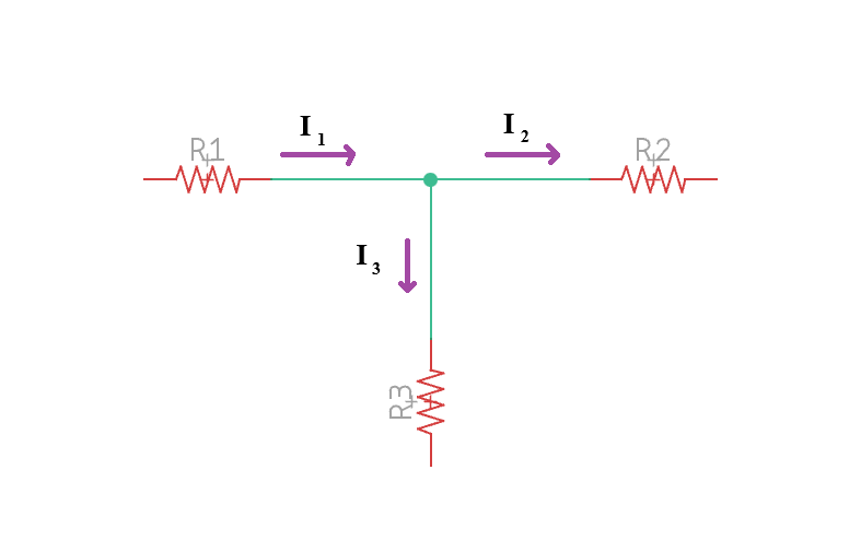
Below is a more common example of a node in a circuit in which KCL would be appropriate. In this example, current flows into the node from the left and then is split into two branches that exit the node. In this case, I1 would be positive as it flows into the node. I2 and I3 would be negative as they are flowing out of the node.

The equation derived in this example using KCL is as follows:
How to Use KCL
Kirchhoff’s Current Law is rarely used by itself. If you have two of the three currents in the above example, you can use KCL to solve for the other current. However, it is more common that you’ll have multiple currents that are unaccounted for and will need to use KCL with KVL to solve the problem. In the next installment, I will work some problems using KVL and KCL to show how they work together.
Thank You
Thank you for taking the time to read this post. I hope that you learned something or at least got a refresher. Feel free to leave questions or comments below. If you like this content and want to see more, please consider subscribing. It really helps me provide more content for you. Or, if you feel we are worthy, consider leaving a tip.
Leave a Reply