
Geothermal Series – Part 3
Introduction
Ground loops are the main component of a geothermal system. We will talk about how to make your own loops, test them, and get them in the ground. If you have not read the previous posts to this series, please do so to be up to date.
Part 1: DIY Geothermal System Design
Part 2: Geothermal Trenches – Digging for Energy
Purpose of Ground Loops
A ground loop is a long pipe or tubing that is placed deep underground. The tubing is usually made out of high density polyethylene (HDPE), but in our case it is made from PEX tubing. The pipes carry a geothermal fluid which is usually water with some additive to prevent freezing. That fluid is what extracts the heat from the A/C unit and carries it down into the ground to be dispersed into the soil.
Think of a geothermal unit like the cooling system in your car. The A/C expels heat much like your car engine does. The geothermal fluid is your coolant, which absorbs the heat of the engine and carries it to the radiator. The ground loops are your radiator, providing a lot of surface area to disperse the heat into the soil.
Length Requirements
To calculate the size of your geothermal ground loops, you need to know the size of your A/C unit in tons. Many A/C units, especially mini-splits, give the size rating in British Thermal Units (BTU’s). To convert this into tons, you need to divide your total BTU’s by 12,000. So if you have a 24,000 BTU system (like mine), you have a 2 ton system.
There is a lot that goes into the sizing of your geothermal ground loop system. There is the composition and thermal conductivity of the soil at the depth of the loops. The type of pipe also has to be considered, as well as the time that the fluid takes to flow through the pipe. I had a lot of unknowns, plus I also had some additives to put in to the trenches to help with the thermal conductivity of the soil. Even with all of that, I decided to go with the rule of thumb, which was to install 600 feet of ground loop per ton. That meant I needed a minimum of 1200 feet of loop.
Building the Ground Loops
Design and Setup
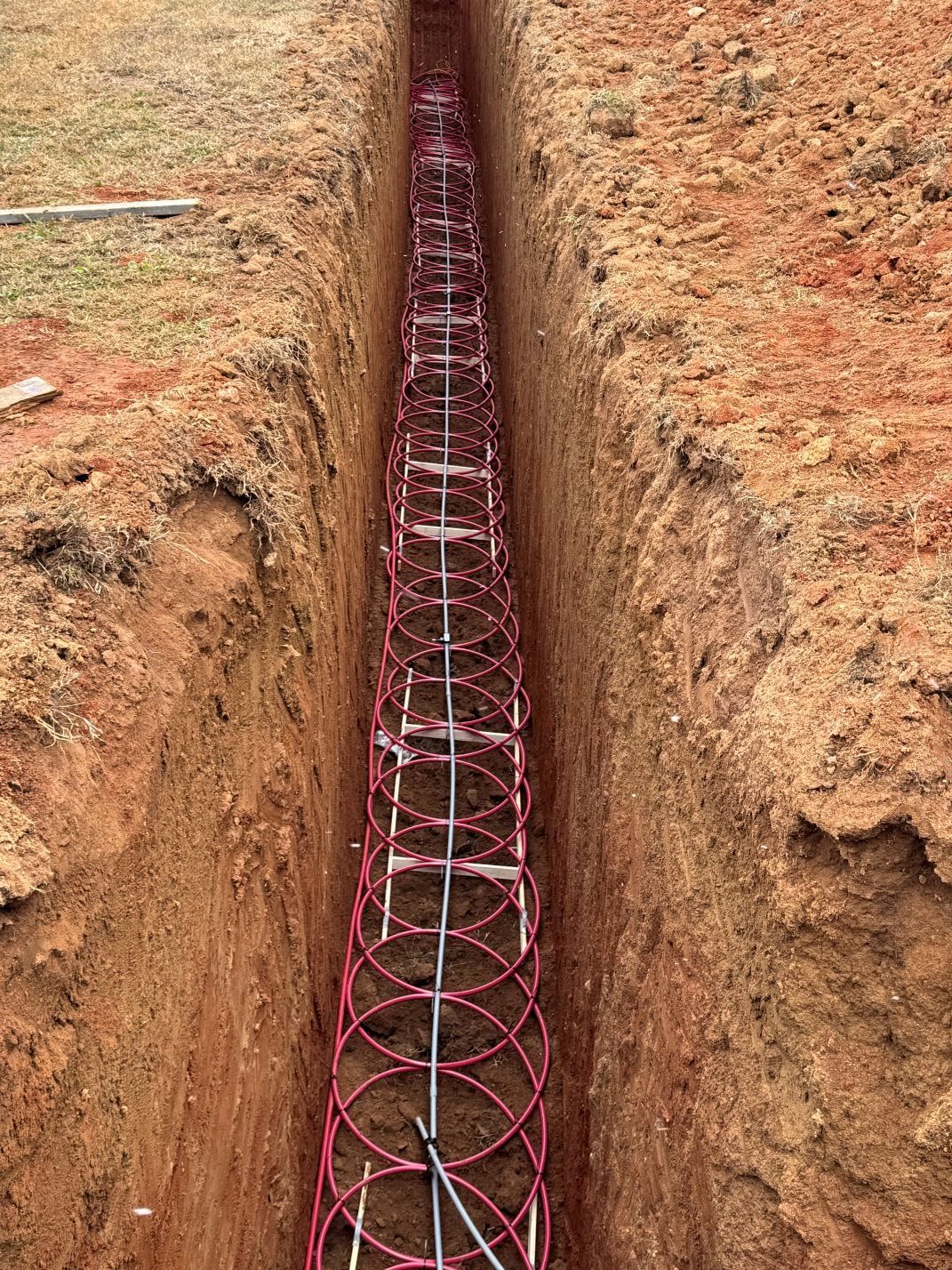
The most common construction method for ground loops is the “slinky” method. With the slinky method, you make the tubing into circles that overlap. This allows you to put more tubing in a smaller area, which saves money. The main cost of the system is not the tubing, but the digging of the trenches. Still, you cannot put too much tubing in one area because you can heat soak the ground. Heat soak is when you disperse so much heat into the soil that it can no longer absorb more heat in an efficient manner.

Construction
In order to construct the slinky, it is important to make sure that they don’t end up wider than the width of the future trench. If you have not read part 2 of this series, please do so. Matching your trench and loop size is important as once they are done, it is difficult to change them.
In order to keep the loop width consistent along the length of the coil, I built a table with guides that were slightly smaller than the width of the trench. I wanted the trench to be 36 inches wide, so I made the guide rails 33 inches wide. It is also important to keep your length consistent. The tubes move quite a bit, even when you use a lot of zip ties to hold them together. Don’t be shy, zip tie! If you have multiple loops, you should try to keep the length of your coils consistent so the trenches will be the same length.

When building your slinky, the longer the run you can do on a single tube, the less chance for failure. Just keep in mind that long coils of tubing can be difficult to handle and if you put a kink in it, it will be more likely to fail. However, I wanted to put temperature sensors in my ground loops to measure water temperature. The sensors are built into PEX connectors, so I could use the sensors as connectors between sections. This made 300 foot coils of PEX ideal.
I also decided to make sure that each of my loops had 600 feet in the loop itself, excluding feed and return lines. The feed and return lines together added another 300 ft to the system, which gave me a half-ton buffer on my sizing.
Testing
Testing the system while it is above ground is very important! If there are leaks at the connections, it is very difficult, if not impossible to fix them without getting down in the trench. I setup a test stand where I used a bucket to act as a tank. The bucket had a drain tube in the bottom that fed the pump, then I connected the tubing to the pump with the return line going into the bucket. After filling with geothermal fluid, and making sure the regulator is actually open, I was able to run the pump for several minutes while I checked for leaks.

One side effect of testing is that the tubes are now full of fluid and that makes them heavy. Unless you want to go through the trouble of trying to get all the fluid out of the tubes, moving the slinky will be more difficult. The slinkies can shift if they are not bound together properly.
Installation
The installation process is not without its challenges. My trenches were 10 feet deep, so setting them down in the trench without them getting twisted or ending up on their side was a challenge. Especially with the added weight of the fluid. In addition to that, I had several sensors, both ground and water temperature sensors and one soil moisture sensor that I needed to worry about.
I also had to put spacers under the coils to keep them off the ground. That would give room for a special ingredient to encase the coils. For the spacers, I just used sections of 1×4’s. I spaced them every 8 feet, but should have put more of them and much closer together.

I wanted to make sure that the slinky was lined up before I dropped it down in the trench. I put boards across the trench and then pulled the slinky out onto the boards, to center it. Ropes were tied to the slinky and to the excavator to assist in dropping the coils down into the trench. Then I went one-by-one down the line, pulling out the crossing boards so that the slinky would drop into the trench.

Thank You
Thank you for reading my post. If you find that you gained some knowledge and would like to read more, please consider giving us a like and subscribing. It’s free and it helps us get sponsors for future content. Also if you feel we are worthy of a small donation, you can leave a tip at the button below. Every little bit helps as the projects can be quite costly.
Leave a Reply